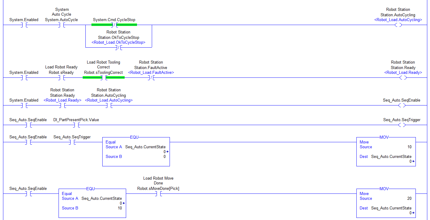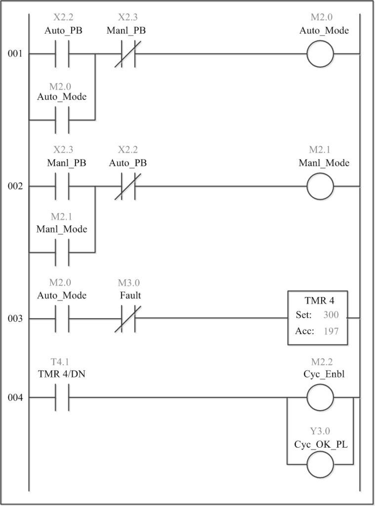


The Structure of Ladder Logic/How to Read Ladder Logic But the cost associated with it in terms of time-consuming logic changes, mechanical failures over time and extensive wiring and space requirements has forced many industries to reconsider their control needs. Relay logic is a dependable controls method still in limited use today. Using this combination of switches, relays, coils and contacts is referred to as Relay Logic. The pump fills the mold with melted plastic and the cube begins to take shape. This switch energizes a relay coil, which in turn closes the normally open contact for the injection pump. For instance, when the cube’s mold is in position a switch will close. The simple opening and closing of relay contacts on the panel gives the system the ON/OFF control it needs in the manufacturing process. These relay panels consist of numerous electromechanical relays that are wired together to perform a certain function in the plant. The relay panels you work on need to be rewired to accommodate the change in production size, from the original 3x3x3 size to the new 4x4x4 model. You have a busy day ahead since the plant is being redesigned for the new Rubik’s Revenge model due out next year. You’re cruising in your brand new Ford Pinto on the way to your job at the local Rubik’s Cube plant. The Origins of Ladder Logic – Relay Logic Different types of programming languages have also been developed for PLCs but the most frequently used is still Ladder Logic. Over time they have advanced to become more user friendly, efficient, smaller and less expensive. PLCs have exploded in the controls market and are used throughout the world.


 0 kommentar(er)
